
I began prototyping this week by mapping out all the individual elements I need to construct for my seed growing lamp, which has become something that will have legs and sit on a surface.
Based on above sketch; left to right, top to bottom:
container for seed cartridges with drainage hole
tall walls with cutouts for visibility (I may seal with clear plastic for humidity)
a fillable water container with a pump and tube that leads up to the top of the structure
a lid with an entranceway for the water pip and cutout to hold a lightbulb
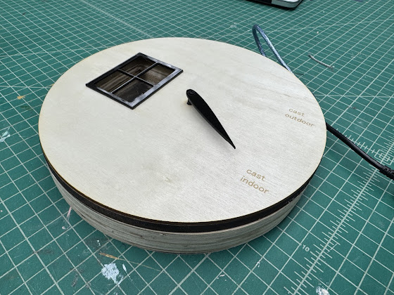
a twisting system of two circles with holes that uses a servo to occasionally and evenly
distribute water across the seeds

To get a sense of dimensions and structural complications, I made a quick prototype of the form I have in mind, scaled down. It led me to this revised plan, which I will move forward with next week:


Mimicking the cardboard prototype, the lamp will be a hexagonal prism with triangular cutouts on each vertical face. The cutouts of those triangles will become legs. Water will be stored below the prism and brought to the top through a tube. Again, the top will contain a lamp.
Below the lamp, a circular dish will be mounted inside the prism; this is where the water will be deposited. A pattern of aligning holes will be cut in the bottom of the dish as well as a circular disc. The circular disc will be placed inside it and controlled by a servo motor. When I want water to be delivered to the soil, the motor will turn to align the holes so that water may fall through. A challenge will be making the dish nearly water-tight when the holes are offset.
I would also like for half of the hexagonal prism to swing open like a door to allow for easy maintenance.
A final fabrication challenge is to make biodegradable, hexagonal trays to start the seeds in.


