A. Lab 1: Electricity Basics
electricity
There are two types of voltage: AC (alternating current) and DC (direct current).
AC is the type of power that comes out of our wall sockets; its power output resembles a sign wave in that it undulates back and forth between positive and negative voltage. Hertz (Hz) is one measurement of the properties of AC power; it is how many cycles between positive and negative the power undergoes every second. For example, all US outlets run at 110 Hz.
DC is the type of power that batteries create, and it outputs a consistent voltage instead of cycling like AC does.
There are several main measurements for aspects of electricity:
Volts (V)
Current (amps - a)
Resistance (Ohms - Ω)
Ohm's law is an equation that represents the relationships between these three aspects:
V = I*R (where V is volts, I is current, and R is resistance)
An analogy to a water hose makes what each value describes more clear: volts are like the force with which water comes out, the amount of water that flows out at an instantaneous cross-section is the amps, and pinching the hose is like resistance.
Another useful equation, about power: P = I*E (where P is power, I is current, E is volts)
how a breadboard works
Using a breadboard helps us to avoid soldering for now, and it works by grasping pins stuck into the board between a metal clasp to create electrical connections. "Lanes" on the breadboard are each labeled by numbers and can make electrical connections.
It's a good idea to shorten things as you place them in the breadboard so that they don't get knocked around.
schematics and diagrams
A schematic is a 2D, technical drawing that uses symbols and lines to represent electrical relationships between the components of an object. A diagram is more representational, and may show how the physical objects themselves relate to each other in space.
components in a flashlight circuit
LEDs must go in a specific direction because they are polarized. A larger piece of metal inside the bulb, a shorter pin, and a flattened edge indicate the negative side of the LED. Meanwhile, resistors are not polarized.
The colored bands on a resistor, read from the one furthest from the metallic band on the resistor to the nearest, indicate the value in ohms of the resistor. the first two bands indicate the first two numbers of the resistor and the third band indicates how many zeroes to add to the end of the first two numbers.
Here is the meaning of the numbers:
Black 0
Brown 1
Red 2
Orange 3
Yellow 4
Green 5
Blue 6
Violet 7
Grey 8
White 9
the flashlight circuit

B. Lab 2: voltage dividing and using a multimeter
Using two resistors can help reduce the voltage in a certain part of the circuit. The ratio of the values of the two resistors to one another determines how much the voltage is reduced. If the resistors are of equal strength, then the voltage will be divided in half. Connecting a lower-level resistor to ground and a higher-level one to the positive column will reduce the voltage to a small fraction of the original; doing the opposite allows most of the voltage through.
This technique is not really for customizing voltage, though. In the future, we'll be using it to send signals.
We also learned how to use a multimeter; by placing the ground probe on a wire connected directly to ground of the power source (with no resistor between that wire and the power source) and the positive probe to a positive wire that has a resistor between it and the power source, it will read as the new voltage.
C. Lab 3: digital input
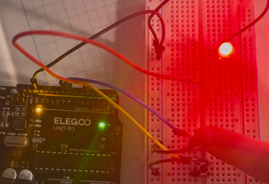
For this lab, I created this wiring setup to use with code that makes an on and off button system for an led:
A pin reading as "LOW" means that it is connected to ground. Perhaps the Low state triggers an action because a button press electrically connects the wire that's in the pin to ground?
This code, meanwhile, sends a serial message when the button changes from being pressed to not, or vice-versa:
Some notes:
-we can't just simplify what's in the loop section to just print the current button state because what we are trying to capture is a change in the button state, not the state itself.
-sometimes multiple messages come through even though the button was only pressed once. maybe this has something to do with the presence of a loop?
-you could change the message to send only when the state goes from high to low by adding an "and" component to the conditional.